CAT, PV panels within roof lights (Bagnall, 2015)


WHAT ARE PHOTOVOLTAIC PANELS?

Photovoltaic (PV) panels (otherwise referred to as Solar Panels) are a growing trend across the world in a bid to adapt to using sustainable technologies. While at CAT, a lecture was presented to us from Arthur Butler on the practical uses of PV Panels and how variations in design and weather can affect the electrical output of them.

PV panels are typically made from a silicon base (covalently bonded together), with boron and phosphorus diffused either side of the silicon. It is the electron displacement caused by the solar radiation (gamma) upon the panel, which creates the electricity. This electrical output (form of a DC current) is then sent through an inverter which turns the electricity to an AC current, this can either be used directly in the property or sent into the mains grid. There are positive and negatives to how you use the electricity; if electricity is sent into the mains grid (also known as a UK Feed-in-Tariff), the government will pay for the electricity you supply into the grid. If the electricity is kept, batteries for these systems have low-efficiency and you will lose a lot of the outputted electricity (through various energy transfers), therefore it is recommended that when you have the panels installed you sign up for the Feed-in-Tariff. 


HOW DO THEY WORK?

Example of PV panels (Bagnall, 2015)
The solar radiation from the Sun is a vast renewable source, however particularly in the UK, due to the weather system we cannot always efficiently harness all of this energy. As people well know, the UK is not always known for its clear, blue skies and is often cloud covered. This results in a different form of radiation which provides the input to the PV panels;


  • Direct Radiation
                                 When there is little-to-no cloud cover between the Sun and the PV panel, and the solar radiation hits the panel DIRECTLY. This allows for a higher output of electrical energy from the panel.

  • Diffuse Radiation
                                  Diffuse radiation relates to when there is medium to high cloud coverage between the panel and the Sun, meaning that the panel will have a smaller input of solar radiation (radiation has DIFFUSED through the clouds, small part of radiation will be absorbed).


As well as cloud coverage (weather), there are various different aspects location and surrounding which need to be considered before installing a photovoltaic panel.
  • Air pollution
  • Solar geometry
  • Diurnal variation
  • Wind direction


APPLICATION OF PV PANELS IN THE UK

In the UK, standardising tests have been performed with panels to judge how to maximise the efficiency of them when used on both domestic and non-domestic properties. These standardising tests have shown that a panel should be at UK average roof pitch of 35 degrees to provide the best efficiency of the panel. Furthermore the tests shown that the placement of the panels upon the roof plane needs to be calculated carefully to stop any damage to the panels; standard measurements state that a 500mm gap on domestic and a 1000mm gap on non-domestic should be left around the panels to prevent wind lift/damage.

When you see PV panels on roofs, there are mostly static panel which are attached to the roof and do not move; this results in a varying efficiency throughout the day due to the sun path across the sky. This has results in the creation of different panel framing.
  • Static – does not move (attached to roof plane)
  • Solar Tracking – allows panel to move on a single axis to follow the sun path
  • Dual-Axis – allows panel to move on two axes, increasing its position to increase efficiency.

 Even though it can be easily accepted that a dual-axis system is better, it is a lot more expensive than a standard static fixing and requires greater room to accommodate its rotation.


TYPES OF PV PANELS

PV panels come in different configurations and sizes, however the generic type of panel can be categorised into three types;
·         Mono-crystalline
Single crystalline silicon made from a silicon ingot (pure silicon); can be identified by its black colour. Efficiency of this panel is approximately 22% (at standard testing)
·         Poly-crystalline
Multi-crystalline silicon/polysilicon; this panel can be identified with its medium-dark blue colour. This panel is cheaper to make that the mono-crystalline, which also results in a lower efficiency.
·         Amorphus
Also known as Thin Film. Sprayed silicon panel with an efficiency of approximate 12%.


APPLICATION TO PROJECT

In terms of applying this technology to my project, I would agree that this form of technology would be ideal. Geographical, the site allows for PV panels to be used, however the weather which the site experiences will need to be considered as well as surrounding context (shading from surrounding building and trees). Nevertheless, the range of photovoltaic panels which are available will provide ways around problems the site brings and makes the use of PV panels (mostly likely mono-crystalline due to higher efficiency) very viable on this project.


COMPANIES/SUPPLIERS

SolarWorld UK - http://www.solarworld-uk.co.uk/products/solar-modules/overview/
EvoEnergy - http://www.evoenergy.co.uk/solar-panels/
Sharp - http://www.sharp.co.uk/cps/rde/xchg/gb/hs.xsl/-/html/photovoltaic.htm


ADDITIONAL LINKS

British Photovoltaic Association -  http://bpva.org.uk/
Bristish Gas - http://www.britishgas.co.uk/products-and-services/solar-panels/solar-pv.html
Energy Saving Trust - http://www.energysavingtrust.org.uk/domestic/content/solar-panels


Solar heating (also known as solar thermal) is the system of where the solar radiation from the Sun is used to directly heat up water within exposed pipework, which is then pumped into a cylinder within the hot water tank to heat the water within the tank. This water is finally used as the hot water supply throughout the property.

According to the EnergySavingTrustUK, trails have shown that using solar (water) heating can provide a domestic home approximately 60% of its hot water demand, although this figure is only an approximation and only considered aspects such as a small family of 4 using the water and the time of day the hot water is in demand (Sun will provide greater heating of water at different times of the day).


TYPES OF SOLAR HEATING

Solar heating can be incorporated on to a property using one of two systems;
  • Excavated Tubes
Using a vacuumed tube made of glass, the water is pumped through metal absorber tubes, these tubes are heated by the sun, which through convection heats the water.

  • Flat Plate Panel
These panels are usually created in a box like structure with a glass/plastic top. The solar radiation passes through the glass/plastic top and into the box, where the pipework carrying the water is fitted into an absorber plate. The box housing is insulated to retain heat; the flat plates heat up through the radiation, which in turn transfer the heat to the water in the pipework.


PRACTICAL EXPERIMENT

Practical solar heating system (Bagnall, 2015)
Part of our CAT week, we were involved in creating our own solar heating, flat plate system with 15&22mm copper pipework, an insulated box and absorber plates. This exercise showed how the installation of the system has to be calculated, while carefully fixed together; like a lot of groups found, once the water was put through the system and pressure applied, if the joint where too loose they would burst, if they were too tight they would leak (Photographs accompanying show completed practical experiment).  

The system itself has approximately a 50% efficiency, which shows how the system utilizes the solar radiation well. To increase the solar absorption, the system will be painted black. The maintenance of the system is generally low-cost too, with most suppliers providing up at a 10-year warranty on their solar heating systems. A certified installer should come and check the system and accompanying water pump ever 3-7 years, the only part which to buyer will need to regularly check personally is for leaks or burst pipework.

Practical solar heating system being heated by sun (Bagnall, 2015)


APPLICATION TO PROJECT

Due to its high efficiency, you could say that this system would certainly be used within the final project. However, because of the size of the project (school) and the size of the systems which will need to be installed to accommodate those within the building, the size of the system will need to be calculated so a space can be created (solar heating system can be placed on the ground flat, however this could result in a lower efficiency, meaning more systems will need to be installed). With choice to system, I feel that using an excavated tube system would allow me to utilise the solar radiation most efficiently. 


COMPANIES/SUPPLIERS 

Vaillant - http://www.vaillant.co.uk/products/renewables/solar-thermal-water-heating/
King Span Solar - http://www.kingspansolar.co.uk/
Dimplex - http://www.dimplex.co.uk/products/renewable_solutions/solar_water_heating/index.htm


ADDITIONAL LINKS

Energy Saving Trust - http://www.energysavingtrust.org.uk/domestic/content/solar-water-heating

You Gen - http://www.yougen.co.uk/renewable-energy/Solar+Thermal/
Light Source - http://www.lightsource-re.co.uk/news/2014/09/should-i-use-a-solar-pv-or-solar-thermal-system/
CAT Reservoir (Bagnall, 2015)

CAT itself is built upon an existing slate quarry. Higher up in the hills houses a reservoir which was used to power the quarry’s machinery.  To present day, that same reservoir is being used to power a larger hydro-electric turbine, providing an electrical supply to the site.

Hydro-electric power is generally produced by the force of gravity-fed water from a high source, spinning a turbine at a lower source (vertically), which in turn generates electricity. It is said that for a large system like this to work, the reservoir water level should be greater than 20m higher than that of the turbine, so that the force which gravity provides the water with is the greatest amount of kinetic energy to power the turbine (smaller turbines can be used at smaller vertical height, however will not produce a large amount of electricity).


CAT’s APPLICATION OF HYDRO-ELECTRICITY

Pipework from reservoir to turbine (Bagnall, 2015)
Referring specifically to CAT, the reservoir they own is 30m above site (calculated through water pressure on site; 1bar = 10m, site pressure of 3bar) where the water provides both electricity through the turbine and drinking water. The reservoir is ideally located, surrounded by slate hills which provide an easy surface run off for all the rainwater. There is also a backup pipe which fills the reservoir from a higher valley, This secondary valley is made up of a chalk soil, also causing an ease run off surface. Due to the 30m height difference, the water builds up a high kinetic energy to power the turbine.

Down on site, we were involved in an experiment with a small scale turbine running off of the reservoirs water. The exposed water wheel of the experiment allowed us to see how by changing the resistance of the electricity (variable resistor connected in series) altered the speed of the wheel; speed of the wheel slowed when more of an electricity demand was asked for. By calculating the voltage, current and rotation speed of the turbine, the efficiency of the turbine could be found and a graph plotted. Once the graph was plotted, it was clearly seen that the turbine was not at its most efficient when at full power, instead at half power (this was then explained to be the case for the majority of turbines) and at that point had an efficiency of 37.75%. This reduction in efficiency could be down to various features of the systems such as the bends in the pipe decreasing the speed and increasing the friction on the water. The friction through the system of the pipework on the water creates a dynamic pressure, which was 0.4bar small (2.6) than that of the static pressure (3.0).

As mentioned previously, as well as powering the turbine, the water is also used as for drinking and cleaning for the whole of the site. As the water in the reservoir is not safe to use, when fed down the pipework, some is separated into a sand bank where the water will filter through the sand, removing the bacteria over a matter of days, finally releasing to be used on site.


APPLICATION TO PROJECT

The concept of using hydro-power system requires a good range of vertical height between the reservoir of water and the turbine to let the water gather enough kinetic energy to power the turbine. However due to the flat nature of the site for the project, the use of hydro-power is not feasible. Furthermore, the electricity per square meter demand of the school will not be met by that of the electricity output from the turbine. 


COMPANIES/SUPPLIERS

Derwent - http://www.derwent-hydro.co.uk/
Renewable First - http://www.renewablesfirst.co.uk/


ADDITIONAL LINKS

Gov. uk - https://www.gov.uk/harnessing-hydroelectric-power
Renewable Energy Centre - http://www.therenewableenergycentre.co.uk/hydroelectric-power/
RWE - http://www.rwe.com/web/cms/en/86920/rwe-innogy/sites/hydroelectric-power-station/united-kingdom/


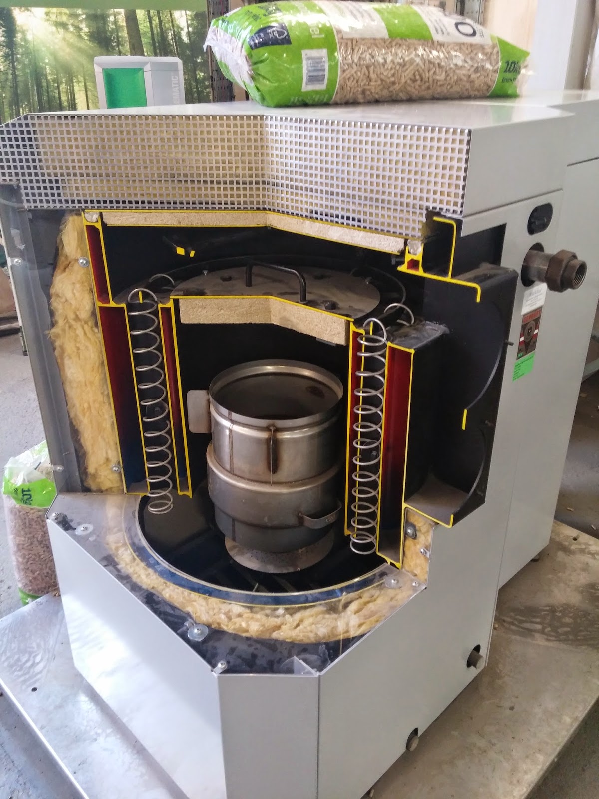
Biomass heaters consists of a specially designed machine burning a form of wood (chip or pellet) where the heat created by this system is used to heat water, providing a hot water supply to the property. As the source of material (wood) goes through carbon sequestration during its lifecycle; when the wood is burned, the release of that carbon dioxide through burning it is equal if not less to that which the tree has absorbed during its lifecycle. The heaters themselves can work between 90-95% efficiency.


BIOMASS AT CAT 

At CAT, we were shown the plant room which contained the site’s biomass heaters which help in water heating. On site they have both a wood chip and wood pellet biomass heater; the difference between the two is the condition of the wood. The wood chips will be of varying size and taken from the tree directly, which means that it also contains various impurities, air and water, which results in a decrease in efficiency of the boiler. However the wood pellets are processed; the wood is broken down to a fine dust and compressed into pellets. The pellets have the advantage of being able to be produced to the same shape and size, which the heaters can burn more efficiently. Furthermore by compressing the wood into pellets, some impurities, the air and water will be removed from the wood meaning the boiler will be able to perform at near maximum efficiency. Wooden logs can also be used within the system, however similar to wood chip, the logs contain impurities, air and water meaning the efficiency of burning it to the energy created to less than using the wood pellets.

The biomass heaters on site are fed by larger hoppers. A hopper will be filled with the wood chips/pellets and will be directly fed into the biomass heaters. One of the main problems when using a biomass heater is that it has to kept running for long periods of time (cannot be turned on and off due to energy required to heat system up), therefore the hopper has to be continually topped up to keep the boiler going. This will result in many deliveries of the wood if not on site, so the hopper will have to be to be loaded from a lorry directly (unless you want to carry the wood….).

CAT's wood pellet biomass heater (Bagnall, 2015)
CAT's wood chip biomass heater (Bagnall, 2015)


CAREFUL CALCULATION

Sometimes it is not practical to use biomass, or sometimes can be over-specified. This is the case in CAT with their large scale heat and electrical biomass heater. This biomass heater so big that the site cannot use it; specifically the heat that the heater produces is too great for the site to handle, and there is no other source in which they can output the additional heat into.


APPLICATION TO MY PROJECT

In terms of its efficiency, a biomass heater is seen as one of the best sustainable technologies from CAT we could incorporate into our school project. Nevertheless, the size in of the project, the running time of the heater and finally the continual topping-up of its hopper in mind, I feel that a biomass heater would not be appropriate for the school in terms of size-to-demand and also its running cost. In addition, due to the refilling of the hopper, there would have to be a member of staff down there the majority of the day in charge of refilling and would spend a lot of time in that plant room. 


COMPANIES/SUPPLIERS

Billington Bioenergy - http://www.billingtonbioenergy.co.uk/
Windhager - http://www.windhager.co.uk/


ADDITIONAL LINKS

Biomass Suppliers List - http://biomass-suppliers-list.service.gov.uk/
Biomass Energy Centre - http://www.biomassenergycentre.org.uk/portal/page?_pageid=73,1&_dad=portal&_schema=PORTAL
Ofgen - https://www.ofgem.gov.uk/environmental-programmes/renewables-obligation-ro/information-generators/biomass-sustainability


CAT, sedum green roof (Bagnall, 2015)

Green roofs have increased in popularity over recent year, but as well as their aesthetic appear, green roofs provide a positive investment into the environment. At CAT, the application of green roofs has been used throughout many of their building, although each green roof composes of different materials which each have their alternative properties.


TYPES OF GREEN ROOF

As a group we discussed how green roofs are spilt into two main categories;
  • Green Roof
  • Brown Roof

A green roof represents a roof which had had greenery place upon it like moss and grass, whereas a brown roof could also have both moss and grass, but in particular contains the plant life which was on (or surrounding) the existing site to which the building sits. Then within these categories of green roof comes two different forms;
  • Extensive

                     An extensive green roof provides a self-maintenance green roof, where a sedum or moss plant life will be placed on top. This green roof is low maintenance and is the lightest per/m2 of any form of green roof.  
  • Intensive

                     An intensive green roof provides a thicker growing medium which allows for the growth of plant life. Grass, small trees and farming plants (fruit and vegetable) can be added on top of this roof, however it comes at a cost of weight.


CAD drawing of both extensive and intensive green roofs (Bagnall, 2014)


PRACTICAL COSTRUCTION OF A GREEN ROOF

A green roof is great as a thermal mass (insulation) on the roof, encouraging plant life and wildlife, adding to the biodiversity of the building, although as mentioned above it comes at a cost. A typical slate roof will provide a load of approximately 150kg/m2, however a typical green roof will on average provide a load on the building of approximately 500kg/m2, over 3x heavier.

In a cityscape, a Thermal Island is created by the escape of heat from the compact building layout within the city; this can result in a temperature different of up to 50 in some areas. In theory, if we were to increase the amount of green roofs within a cityscape, it would not only reduce the loss of the city and decrease the thermal island effect, but also help reduce the accumulation of CO2 produced within the city.


APPLICATION TO PROJECT

Within our brief, the client has requested at least one green roof space on top of the school. At design and planning stage, it can be argued that there is room for two separated green roofs on top of the building, where each green roof could provide different functions; one extensive for walking upon or using as a social space, and one intensive to be used for food growth. However this is dependent on the school kitchens (whether they will be incorporated within this extension or not) and the policies of the school to grow their own food. The load in which these roofs will create should not be an issue due to the primary frame being cast in-situ concrete.


COMPANIES/SUPPLIERS

Bauder - http://www.bauder.co.uk/green-roofs
Sedum Green Roof - http://www.sedumgreenroof.co.uk/
Blackdown Green Roof - http://www.blackdown.co.uk/green-roofs/


ADDITIONAL LINKS

Green Roof Guide - http://www.greenroofguide.co.uk/
Green Roof Centre - http://www.thegreenroofcentre.co.uk/
Earth wall as second skin for lecture room  (Bagnall, 2015)
CAT, the Centre for Alternative Technology doesn’t just look at renewable technologies and utilising them (for example, solar radiation and water to create electricity), but also how to construct in alternative ways which have a smaller impact on the environment. It is a known fact that concrete and steel is one of the major areas of the construction industry which creates the greatest amounts of carbon dioxide in the UK. At CAT we were taken on tours around their site to show how they have used alternative construction materials to build building.


SOLAR GAIN

The tour was done by Trisha Andrews, an architect who has worked with CAT for over 25years. Her tour started at looking how the orientation of a building can contribute to the building's internal thermal comfort. We discussed how a buildings south façade should be fitted with the most glazing compared to the other surround façade, this is to introduce a solar gain factor to the building. Solar gain looks at providing a thermal energy into the building as well as a light, so the solar radiation heats the building up as well as providing natural sunlight. By adding more glazing to the south façade, this means the benefit from a greater solar gain (sun path of the UK).


STRAW BALE CONSTRUCTION

After solar gain, we moved to the next building on the site which was one made of a latch primary frame with the main material of the walls constructed from straw bales. Trisha told the group how compact, building straw bales where used during the construction; these building bales allow construction up to 2 and a half storeys high, while also providing a good insulation to the internal building. The straw bales are an unusual form of construction material and are quite thick, however with its insulation value and how cheap it is (£10,000 worth of bricks could be replaced by £600 worth of straw bales), could mean it becomes a popular building material in the future.


TIMBER FRAMING 

From straw bales we moved onto timber frames. While looking around at the surrounding Snowdon landscape, it was quite apparent that there was a problem with the trees as seen by their colour. We were told how the latch population within the UK was dying through a disease, and latch needs to be used in the next 5-10 years, after that there may not be any latch left to use. While looking at an exterior timber frame by the visitors centre, we spoke about the different treatments which are applied to the wood before use, and how the treatments may not always be the best treatment for the wood. The wood on site used on this frame was not treated but left to dry before use (making it structural harder), however in the UK we previously used a CCA (chrome, copper and arsenic) treatment which poisoned the trees. Although now we use a CCB (chrome, copper and boron) treatment which is less toxic (still slightly toxic) and can be applied in three different ways; dipped, brushed or pellet inserted.


EARTH WALL

The final part of the tour looked at we use of Earth Wall within the visitors centre and the new WISE building. The Earth Wall was created by ramming sand, clay and water together, compressing a 100mm mixtures of the three materials into a 50mm, dense block. The wall was created in layers, each layer rammed and the next layer applied until the wall is complete.


APPLICATION TO PROJECT

As the primary structure of our final project has to be 3 storeys and made from a primary cast in-situ concrete frame, it rules out using latch completely and straw bales partially; the reason I say partially is because the straw bales could be used as a secondary walling between the concrete floor slabs. I feel that the only use of the earth wall would be in a sculpture but I would not consider it viable to use it as primary or secondary walling. 


COMPANIES/SUPPLIERS 

Strawworks - http://www.strawworks.co.uk/ [straw]
ModCel - http://www.modcell.com/ [straw]
Sirewall - http://www.sirewall.com/licensees/earthwall-rammed-earth-architecture/ [earth wall]


ADDITIONAL LINKS

University of Bath - http://www.bath.ac.uk/research/case-studies/straw-scientifically-proven-building-material [straw]
VSL - http://www.vsl.com/business-lines/ground-engineering/vsolr.html [earth wall]


Here I have included a selection of photographs which i feel provide a greater depth of what CAT is and what they are trying to do. All photographs taken by myself unless otherwise referenced (Bagnall, 2015).

CAT - Sectional Drawing (Borer, P. 2015)
CAT, Central courtyard


Eco-Cabins 

PV panels above WISE building


CAT, Cafeteria 

CAT-Cafeteria 


WISE front space


WISE, Roof Lighting


WISE lecture theatre roof light


WISE cafeteria and lecture roof
WISE cafeteria roof

WISE building foundations

WISE building foundations (close-up)